
XWORKS 70 xFrame Builder's Guide
This installation guide is for the XWORKS 70 xFrame case. It is recommended you follow the steps in the suggested order to ensure a great building experience.
If you find a specific step to be unclear, please reach out and we will adjust for everyone.
Step 1 - Unbox & Identify
For easier building process, let's identify all the parts of your 70 xFrame case. The names used here will be referenced throughout this guide.
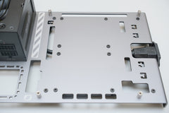
The upper box layer contains the first central frame panel (A) used to attach most of the key component of your system (Motherboard, PSU, 2.5" drives). On the right side you can find the PSU routing area sidewall.

The middle box layer contains the box of screws, two long rods, the PSU Support, the PSU extension cable, and the GPU support bracket. Note: be very careful not to scratch the end of two long rods when removing the middle box layer.


Once removed, the middle box layer unveils the second central frame panel (B) used to attach you GPU and accessories. The lower box layer houses the remaining rods and the routing area cover panel.


Each screw type is highlighted on the Screw-Box cover. Some might look similar but have slight difference. So be very careful to identify them and follow this guideline when building.

Tools Required?
While we provide a tool that is compatible with all screws for the case, you can use your favorite screwdriver and pliers.
- All the silver "fancy" screws use 6-star TORX T8 screw bit (TR8 & T8H should be compatible too)
- All black screws (small) are compatible with a Metric HEX H2 screw bit (or SAE 3/32")
Assembly can be done with the TORX wrench provided with the case. Pliers and electric screwdriver are not included in the package and used for representation only.

It is recommended to have the motherboard, CPU, air cooler pre-installed to simplify cable routing when assembling the system. Once attached to the chassis, the backside of motherboard is not accessible.
Step 2 - Central Frame Assembly
A - Motherboard Support
- 4x F screws
- 4x G silver rounded standoffs
- Attach to central frame Panel A
Tip : The F flathead screws attach from the inside of the panel.


B - Inner Frame & Standoffs
This will ensure your central frame is sturdy once all your components are attached.
- 1x B countersink screw
- 1x G hexagonal standoffs
- Attach to central frame Panel A in the corner next to the small square hole (see schema)
Tip : The B cone-head screws attach from the outside of the panel.


Warning: the next step uses the same standoff but a different screw type.
- 5x F screws
- 5x G hexagonal standoffs
- Attach to central frame Panel A (see schematic)
- The standoffs are attached from the inside of the panel


C - GPU Riser Support
- 2x F screws
- 2x G silver rounded standoffs
- Attach to central frame Panel B (see schematics)


D - Power Button & Routing Area
- Power button
- 4x C screws
- Routing panel (rectangular, engraved)
Tip : The rubber O-ring is used between the routing panel and the nut (at the back of the panel).


With the C screws, attach the routing panel to the PSU cable cover (U-shape sidewall with the XWORKS logo).


Tip: The power button should be the closest to the XWORKS logo. This piece is not attached to the central frame yet.
Note: Tighten the high-gloss screws gently, do not over-tighten them.
E - Power Supply Bracket
On the central frame panel A, insert the PSU bracket into the two square holes.
- 2x B screws


Step 3 - Power Supply Installation
- 4x D imperial countersink screws
- 2x B screws
- PSU extension cable
- Cable ties
Install PSU with 4x D screws. These are imperial screws with coarse thread. Do not mix with other countersink screws.


Install the power extension cable to the same central frame panel with 2x B screws and plug to the PSU. Switch on the PSU if it has a standalone power switch.


Tip : The socket is fixed on the outside of the panel.


Tip : Keep it tidy! Use cable ties and tap on the central frame panel (A). You don't have to flip the central frame panel to tighten the cable tie.
Step 4 - Storage Drive
-
8x F screws


Tip : Install your 2.5" storage before doing all the cable routing for a cleaner result. The connectors of disk drives must face the power extension cable socket (as seen in picture).
Step 5 - Cable Management
A - Power & storage cable
You will need :
- Cable ties
- Creativity

There is no one-size-fits all when it comes to cable management but here is our suggestion:
- Connect all the required PSU cables (modular PSU).
- Route & secure the ATX24/EPS/GPU power cables with cable ties.
- Connect & secure all storage data cables.
- Connect & secure the storage power cables.


Tips: Securing the storage power cable last will make routing easier.
Note: Cable ties should not protrude outside of the central frame panel edge.
B - Routing Area & Cover
- 4x F screws
Secure the routing panel (assembled in Step 2 E) with 4x F screws.


Tip : Pass the Power Button cable in the rectangle hole near the engraved stripes.

At this point you should have all your power, data cables & power button cables on the same panel side as the PSU.
C - GPU Riser
While the GPU Riser might require some bending/adjustment, be gentle to avoid damage. The riser is designed to fit perfectly with the case.


Tip: Pass the male end of the cable into the opening at the top of the frame panel from the back side.
Step 6 - Install Motherboard
- 4x F screws
For easier installation, we recommend that you plug all the cables before securing the motherboard in place, include the PCI-E riser.
All cables include :
- Power cables : ATX 24-pin / EPS 4/8-pin.
- Storage cables.
- Power button cable.
- PCI-E Riser.

Secure the motherboard with the F screws and install memory modules.


Tip: At this point you can adjust your routing inside the central frame as everything is connected where it should (except the GPU).
Step 7 - Central Frame Assembly
Assemble the two panels (A + B), pass the PCIe riser female end and the GPU power cables in the corresponding opening.

A - GPU Riser
- 2x F screws
Secure the PCIe Riser with 2 F screws.

B - Close the central frame
- 6x B Screws
After this step your central frame will be secure & robust, all cables should have been plugged and ready to go (excluding your GPU).


Use the B screws to close the central frame (see schematics).

Step 8 - GPU Installation
Slide the graphics card in the riser socket and connect power cables. If the GPU does not slide into the riser directly, it's possible the PCIe riser lock is "closed".


Tip: Once GPU is installed, close the riser lock again to keep your GPU in place even if you decide to put the case in a non-conventional angle.
Secure your graphic card with:
- 4x thumb screws
- 2x thumb nuts
- GPU support bracket


For ease of installation, we recommend this order:
- Attach the GPU support bracket to the central frame with 2 thumb screw (keep loose a bit).
- Insert the thumb screw from the bottom and use the thumb nut at the top
- Attach the graphics card to the bracket.
- Secure the bracket to the case.
Step 9 - The Outer xFrame
Keep in mind that for all the steps here, you should tighten the screw gently to not damage the rod threads or the screw heads.
A - Pre-assemble Sides (x2)
The sides will carry the central frame and allow for adjusting space allocation between your graphic card & system cooling.
There is two sides, each with (2x):
- 2x small rods (with the notch & holes in the middle)
- 2x medium rods (with no notch)
- 4x E screws
Place one medium rod with the inner-hole facing up and the hole closer to the rods-ends facing toward the small rods (see pictures).


Repeat with the second medium rod with the inner-hole facing up and the hole closer to the rods-ends facing toward the small rods (see pictures).

Install the second small-rod & align the notches in parallel.


Tip: You can check that the assembly is correct with this check list:
- The 4 screws are visible on the same side
- The 2 notches & holes have the same patterns
- The holes on the medium rods are all facing towards the notch
Repeat this process a second time.

B - Attach Central Frame
- 4x A screws
Align the pre-assembled sides with the central frame with the standalone hole on the notch facing the system/power supply side.

Tip: the A & E screws are very similar but the A screw have a smaller head. If the screw seems to short when assembling this step, it might be because you are using the wrong screw.
Secure the other side with the same alignment, check the holes on the notches are aligned correctly to proceed.

Depending on your system or graphics card cooling, you can adjust the hole position. Always align the central frame on the exact same hole on each sides to ensure structural integrity and avoid damage.
C - Finish Assembly
- 8x E screws
- 4x long rods
Assemble the four remaining long rods: Align the notch and secure gently.


Tip: All the long rod should be inward of the medium rods and outward of the small rods.
Step 10 - Enjoy
Send us your build images, so we can share with the rest of the community.
Tip: use the pads on the rods' end depending on your your preferred case positioning.
Warning: please use power cable with ground pin, and to ensure the whole computer is properly grounded prior to power up.
After pressing the power button, the circular LED on the button should light up. If the LED does not light up, check the following:
- If the power button LED is plugged into the correct socket with the correct polarity.
- If the LED is being disabled in BIOS setting.


